Roof From Walls

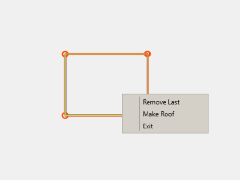
A user picks roof reference walls in a sequence (clockwise or counter- clockwise) then they will right click to select the walls they want planes on. Then a right click will bring up the menu below.

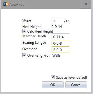
Clicking on Make Roof will bring up this menu for a user to populate the fields with roof information. Once doing this clicking OK will automatically put planes on all of the walls or members selected. Then the next step will be to Cut Roof.

Auto- Cut

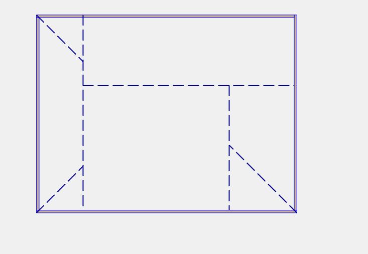
If a user has selected Auto-Cut in the Roof Plane menu (during Roof Plane input process) the software will try and Auto-Cut the roof planes that the user has defined.
If the user has not checked the Auto-Cut field in the Roof Plane Menu Auto-Cut cannot be utilized.
Roof Girder Load
(Roof Truss Girder Loading Macro Only)

Loads input in this section will be used for gravity load development throughout the structure. The software will try to pass all these loads through to levels below.
This tool allows the user to get Roof Loads without having to hand calculate and hand input Roof Truss Loads.
Using Roof Area Loads will automatically create the loads for your Roof Truss Girder as long as the Roof Area Load is touching that girder. So the user does not need to input any loads on the girder if they are going to use the Roof Area Load macro.

Then the user will input Roof Truss Girders using coordinates and angle snaps to ensure the girders are connecting to each other and to the walls properly.

Roof Area Load

A user fills out the additional load menu for Roof Area Load. The user can attach this load to the layout and define truss direction so correct bearing locations will be specified for the roof truss area load to be applied. These reactions will pass down through the structure.
Loads input in this section will be used for gravity load development throughout the structure. The software will try to pass all these loads through to levels below.

The User defines the Area Load by hovering over a specific area they want to insert the Area Load in and moving the mouse slightly to ensure the area load is completely in that area.
The software will not always be able to define every boundary for the Area Load. At that point a user can then edit that load by adding points and moving points so that the boundary is complete.
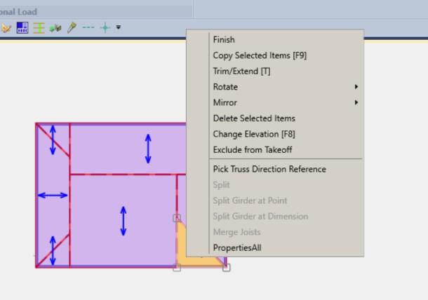
After the user is satisfied with the boundary of the Area Load the user then selects the Area Load and right clicks to Pick Truss Direction Reference. Once clicking on Pick Truss Direction Reference the user picks a segment they want the Truss Direction Reference to be parallel to.
Below shows an example of the right click menu for a user to select a parallel side (member or wall) for the Truss Direction.
